- REVIEWS
Displays Electronics 
Speakers Sources Other Gear Software - HOW TO
How To Buy How To Use Tech 101
How We Test: Audio
Electronics: A/V Receivers
We first connect the A/V receiver, surround processor, or amplifier to be measured, otherwise known as the Device Under Test (DUT), to AC power through a dedicated 20-ampere branch circuit. We plug in the DUT through a variable-mains autotransformer, which lets us adjust the input voltage to a measured 120 volts RMS. This provides for consistent line voltage for all components tested. For AVRs and amps, we connect hand-selected and matched wire-wound, low-inductance power resistors to each loudspeaker output to act as loads for the amplifiers. An Audio Precision audio analyzer is connected to the analog CD input and loudspeaker outputs, and a DVD player is connected to a TosLink optical digital input. A video display is also connected via HDMI or composite video output as needed to navigate onscreen menus.
The DUT is set to nominal parameters throughout the menu system, with all room correction, user EQ, level, distance, and tone controls defeated or zeroed. Inputs and decoding modes must also be set correctly. Once the settings are completed, we disconnect the video monitor from the DUT and power it off to avoid any possible signal contamination during testing.
We select the listening mode that bypasses as much signal processing as possible and adjust the DUT’s volume control to produce as close as possible to a 2.83-volt RMS output with an 8-ohm load and a 0.1-volt RMS 1-kilohertz input. Why those numbers? We use 2.83 volts RMS as the targeted output because calculations tell us that 2.83 volts RMS across an 8-ohm load produces the industry-standard output level of
1 watt. The 0.1 volts chosen for the input signal is a nominal analog input level compatible with most consumer audio gear. And 1 kHz is commonly chosen as the test frequency because it’s roughly the middle of the audio band. After the initial adjustment, we then finely adjust the level of this input signal via the output of the Audio Precision analyzer to produce exactly the desired 2.83-volt RMS out.
SNR, FR, THD & Crosstalk
After a warm-up period for the DUT, the Audio Precision analyzer first measures signal-to-noise ratio (often abbreviated either S/N or SNR). The SNR tells us how loud the unit’s background noise will be versus the actual audio signal; a quieter amplifier has less potential for hiss, hum, and other unwanted noises that can obscure details in the audio signal, especially at low listening levels. The number we call out is the level of the noise relative to the signal, so it’s represented by a negative number. A typical figure is in the range of –90 to –110 decibels. For comparison, the maximum SNR of a standard 16-bit audio CD is 96 dB, while a 24-bit recording is theoretically capable of 144 dB SNR, although that is rarely achieved. SNR is measured in bypass mode (meaning the listening mode with no processing or the least amount possible), and we utilize multiple grounding schemes involving different combinations of tying together signal grounds, the mains ground, and the chassis of the DUT itself. While it’s time consuming, we do this trial-and-error ground optimization to find the configuration that minimizes ground loops and other forms of induced noise so the measurements we publish represent the performance of only the DUT. We then perform the rest of the tests using this same grounding arrangement.
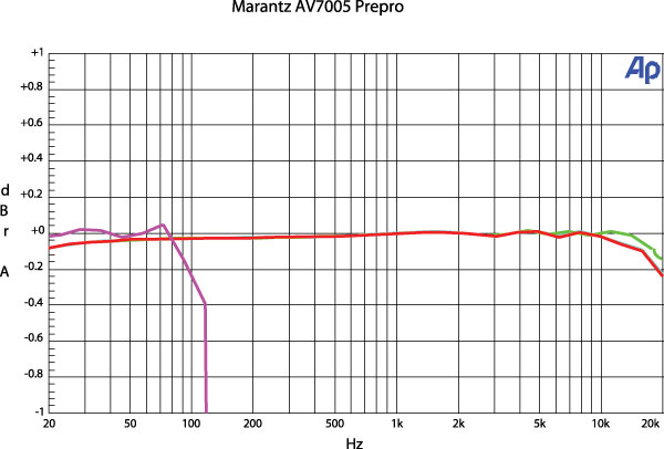
We measure analog frequency response in bypass mode from 10 hertz to 50 kHz, then again in a mode that utilizes signal processing, and finally one last time through the multichannel input if provided. As many Home Theater readers already know, frequency response refers to how well a component passes or reproduces the full frequency range of its input signal without unintentionally boosting or attenuating any given frequency, which could lead to sonic colorations. A loudspeaker’s measured frequency response typically shows peaks and valleys across the audible spectrum, but good amplifiers should measure mostly flat across the recognized human auditory range of 20 Hz to 20 kHz and beyond. No humans can hear out to 50 kHz, so why do we measure out that far? Aside from verifying manufacturers’ claims, and the fact that the latest audio formats are capable of encoding signals that extended in frequency, we know that what happens to the signal beyond the audible band can have effects that reach back down to where we can hear them. We like to know what the performance is like beyond the bare minimum.
After frequency response, we measure total harmonic distortion plus noise (THD+N). In simple terms, this describes the unwanted, harmonically related distortion and general noise that the DUT inadvertently adds to the desired audio signal. While most modern solid-state gear will produce a result of only a tiny fraction of a single percentage point, exotic gear that’s highly respected for audio quality has been known to produce results of over 1 percent on this test. Readings well under 1 percent are considered typical, though. The reasons for this seeming discrepancy are two-fold. The first is revealed in the name of the test itself: THD + Noise. The single number that expresses the result gives no clue as to how much of the stated percentage is relatively innocuous random noise and how much is distortion that’s harmonically related directly to the signal being reproduced. The second missing detail in this standardized test is the nature of the spectral content of the distortion. Not all forms of harmonic distortion are equally audible or objectionable, and a single specification can’t convey this. We do this measurement with the DUT in bypass mode, feeding it that industry-standard 1-kHz input signal at a level that drives 2.83 volts into an 8-ohm load.
While still in bypass mode, we measure crosstalk by injecting a signal into the left channel for a 2.83-volt RMS output at 1 kHz and measuring how much of that signal is present in the right channel, and vice versa. Of course, any bleedthrough from one channel to the other should obviously be minimal, well below the 0-dB reference level. For comparison, a good phono cartridge will likely produce a crosstalk reading of only –35 dB (that is, just 35 dB below the reference level), while a standard audio CD can achieve more than –90 dB. At Home Theater, we consider readings below –60 dB acceptable.
We then measure Dolby Digital frequency response on a selection of channels. We use an optical connection to the DUT, once again to minimize the potential for ground loops and induced noise.
Amplifier Power
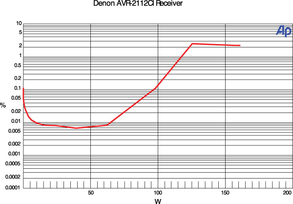
Total harmonic distortion versus amplitude completes the set of tests. We quote power output at 0.1 percent and 1.0 percent distortion levels and measure with the left and right channels driving 8-ohm and then 4-ohm loads. For multichannel amps, we typically measure five channels driving 8-ohm loads and seven channels driving 8-ohm loads. All of these tests utilize continuous, in-phase, 1-kHz sine waves as a stimulus. Line voltage is adjusted to be no lower than 120 volts RMS at maximum amplifier power output.
In the case of home-theater-in-a-box (HTIB) electronics, we measure left and right driven with both 8-ohm and 4-ohm loads and quote output at both 0.2 percent and 1.0 percent THD. The former was necessary as some HTIBs have THD greater than our usual 0.1 percent at any output level. And we don’t usually do multichannel measurements on HTIBs, because they rarely provide analog or uncompressed digital inputs allowing access to more than two channels.
You may wonder why we quote power output at two different distortion levels. The majority of manufacturers use negative feedback in their amplifier stages. The use of negative feedback can have the effect on the amplifier’s output signal of smoothing frequency response and decreasing steady-state distortion, among other things that can ultimately affect the amplifier’s tonal balance. So manufacturers who use negative feedback like to quote maximum power at a low distortion number because that’s where their units look most impressive on paper.
On the other hand, those who use little or no negative feedback in their circuit designs like quoting at 1 percent or higher (due to the nature of their products’ distortion-versus-output profiles). Vacuum-tube amplifiers are often quoted at 1 percent as well. We give you both measurements for comparison. For perspective, the output power of car stereos, HTIBs, portables, and sound systems is often specified at 10 percent THD. Even casual listeners will generally object to more than 10 percent THD, but many are surprised to find that with complex program material played in normally lively rooms, vanishingly low levels of THD aren’t mandatory for a satisfying experience.
We measure and publish RMS continuous amplifier output with a specified number of channels driven in phase. This is in the spirit of the original 1974 Federal Trade Commission (FTC) mandate that standardized amplifier measurements in an effort to protect consumers from misleading audio power specifications. Here lies a point of contention that’s been brewing in our industry for decades: movies and music are unlikely to ever make such brutal demands on an amplifier as our test signals do, so why engage in such unmitigated torture of innocent semiconductors? This is what’s known as a synthetic test, in that it doesn’t represent the demands of real-world program material. But it does generally give insight into the total capabilities of the oh-so-important (and relatively expensive) power-supply section hidden inside. We can’t unequivocally state that your enjoyment of a given movie will be diminished if you use an AVR that has no more total power available when continuously driving seven channels than it does when driving two, for instance. However, we do know we’d be much less concerned about getting our money’s worth when such a condition arises with a budget AVR than with a top-priced model.
Our industry also uses other, less demanding power output tests, but there often isn’t enough commonality or specificity in the stated conditions of testing to meaningfully compare output numbers from different sources or methodologies. Keep reading regularly, and you may start to see a pattern of manufacturers whose claimed numbers tend to track more closely than others to what we measure. We leave it up to you to decide if that’s a good thing or not (nudge, nudge).
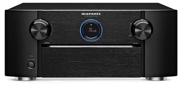
Measurements for surround processors and power amplifiers are mainly subsets of the above A/V receiver tests, with the notable exception that balanced audio connections are often available, so we use them during measurements whenever possible. For power amplifiers, we also measure the gain (essentially the multiplication factor of the audio signal) through both single-ended inputs (typically an RCA connection) and, when available, balanced XLR inputs.
|
| |||||||||


| Displays Electronics Speakers | Sources Other Gear Software | Top Picks of the Year Top Picks | Custom Install How To Buy How To Use |
Tech 101
|
Latest News Features Blogs | Resources Subscriptions |
WHERE TECHNOLOGY BECOMES ENTERTAINMENT
 © 2026 Sound&Vision
AVTech Media Americas Inc., USA
All rights reserved