What are Cables? Cables can be the Weakest Link in the signal delivery process. The cables used can improve the dynamics of the music, give more detail and a convincing recreation of the performance as it was recorded.
What are the basic characteristics of cable design. At this learning center, we will go into detail on the primary characteristics of cables and how they affect performance.
The intent of cables isn’t to improve, but pass along the information with out adding a filter of any kind. The best cables are those that are completely transparent and don’t add or affect the sound or video it is purposed to pass along.
Electrical Properties
Cables have three basic electrical properties: Capacitance, Resistance and Inductance. These properties are interrelated, if you change one, you may have an effect on one of the other properties.
Capacitance
Capacitance is the amount of electrical charge that is stored under an electrical pressure or voltage. With cables and wires, each length of wire has capacitance. Typically the amount of capacitance in wire is small and is measured in picofarads. This capacitance acts as a filter and the greater the capacitance the larger the affect on the signal being transmitted through the cable..
Resistance
Resistance is the opposition to current flow and is measured in ohms. The lower the number (over the same length of cable), the lower the cables resistance to the flow of the signal. There is no wire available that is without resistance. Since we can measure this characteristic, we can determine what effect it will have on the signal.
Resistance and Type of Material
The resistance in the wire varies with length and the type of material used in the wire. For example, copper has a different resistance than silver. Specific types of copper also have difference resistances depending on the purity of the metal. For example, a highly conductive form of copper used by Ultralink/XLO is Electrolytic Tough Pitch or ETP Copper which is usually 99.95% pure.
Inductance
Inductance is a more complicated electrical property. Inductance is measured in henries and is the result of an electromagnetic field being created by a wire when electrons move through the wire. You can increase the amount of magnetic field by coiling the wire. These electromagnetic fields are a fundamental part of how most phono cartridges and loudspeakers function
So why are these three electrical properties important? They all affect the signal.
Capacitance produces capacitance reactance with AC voltage. This reactance becomes more reactive as the frequency is lower. This is how a capacitor works in a speaker’s crossover. As the frequency goes lower, the reactance becomes higher. Therefore in a simple crossover network, a capacitor will prevent low frequency information from reaching a tweeter. The value of the capacitor, along with the characteristics of the speaker driver, will determine the frequency and slope of this crossover.
The inductance produces inductive reactance with AC voltage. This inductive reactance has the opposite of the capacitance reactance described above. An inductor becomes more reactive at higher frequencies. Therefore, an inductor used in a speaker’s crossover will prevent higher frequencies from reaching a specific speaker driver.
Resistance and the Size of the Wire
The resistance of the wire depends on the type and amount of material used in the cable’s construction. With speaker wires the American Wire Gauge (AWG) standard is usually stated. This gauge is a measurement of the size of the conductor. The smaller the number the thicker the wire. For example an 18 gauge wire is larger than a 24 gauge wire.
A thinner wire has more resistance to electrical flow than a thicker wire. For example a standard 24 gauge wire will typically have a resistance of 0.05 ohms per foot where an 18 gauge wire will have a resistance of 0.014 ohms per foot. The effect of this resistance is additive, meaning the resistance of the wire is added to the resistance of the loudspeaker. Therefore, when the power stage of the amplifier is driving the speaker system, the full power of that amplifier will not be received by the speaker system. As an example if we use a 25 foot length of 24 gauge speaker wire, it will typically have a resistance of 1.25 ohms. This additional resistance will be dissipated as heat by the wire. If we change the 24 gauge wire to an 18 gauge wire, the resistance will be only 0.35 ohms and therefore more signal will reach the loudspeaker. What becomes even more significant is that a loudspeaker does not have a flat impedance curve throughout its frequency bandwidth. In this example the curve shows a value throughout the frequency range of 2.5 ohms to 22 ohms. If the cable is adding a resistance to the speaker system then it will have a greater impact on the signal transfer at 2.5 ohms than 22 ohms. If the value of the resistance in the speaker cable is lower 0.35 ohm, with the 18 gauge wire, rather than 1.25 ohms, with the 24 gauge wire, the sonic effect of the resistance will be less in both output of the speaker and its frequency response. Therefore, thicker, lower resistance cables will have less effect on the sound than the thinner, longer cables.
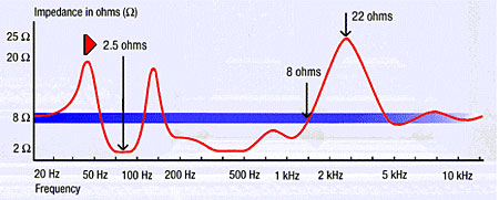
The effects of this change in power will be greater when the impedance is low, 2.5 ohms for example, then when the impedance is high, 22 ohms for example.
As you can deduce from these electrical characteristics, the cable’s designer has to balance the electrical properties of the wire to give the best possible sound. Since all wires have these three electrical properties, the construction of the cable and the length all have effects on the signal going through the wire.
Conductors
The type of material used in the conductor is typically either silver or copper. Silver typically has a lower resistance than copper, but not all coppers are created equally. The higher cost of silver is not always a factor since very pure copper can be more costly than silver.
Dielectric
The dielectric (material surrounding the cable) used will have an effect on how signals are sent through the cable. A dielectric with a higher dielectric absorption can degrade the sound by absorbing the signal and then releasing the signal back into the conductor. , The dielectric effect is similar to that of the dielectric in a capacitor used in audio circuits. Different materials have different absorption characteristics and whether the material used as the dielectric is in a cable or capacitor, it has an effect on the signal.. Teflon is one the materials that has low dielectric absorption and is one of the materials used as a dielectric in high quality cables. Ultralink and XLO use Teflon in many of their cables including the Ultralink HDMI Pro II – 1.3 and the XLO HTProHDMI
Skin Effect
Skin Effect is the characteristic of wire to have high frequencies travel along the outside surface of the wire and less high frequencies traveling along the center core. The effect is that frequencies do not travel equally throughout the total diameter of the wire. There are methods of constructing cables to minimize the skin effect.
Cable Construction
How the strands of a cable are constructed can also have an effect on performance. By constructing cables in certain configurations, you can affect the electrical characteristics. For example, by having a lower inductance, you will typically have a higher capacitance. Higher inductance can achieved lower capacitance. There is no right or wrong --- it depends on the goals of the designer.
Safety Standards
In AC power circuits, standards are used for the size of cable required for different current loads at specific voltages. Most electricians use 14 gauge wire for a 15 amp 120 volt circuit and 12 gauge wire for a 20 amp 120 volt circuit. These standards assure that the wire will not overheat or be used above its capacity. In the US, standards for speaker wire or interconnects are not typically published when the cable is used under most free air conditions. When cabling is used in enclosed areas such as ceilings, walls, crawl spaces, there are fire code standards. When a cable passes the CL2 ,CL3 and/ the FT4 vertical flame test standard for enclosed space use, rating is typically impressed or stenciled on the jacket of the cable. If you are planning to use any cables under enclosed conditions, you should check with local codes to make sure the cables you use meet applicable standards for your area. When using high current, high power amplifiers,, a lower gauge (thicker) wire should be used to handle the current. This does not necessarily mean that the wire passes fire and flame test codes for your locality.
75 Ohm and Optical Connections
Most of the above information relates to how wire or cable is used in an analog audio music system. There are also considerations for digital music systems.
In these systems, a 75 ohm cable is usually required. Make sure the cable is intended for this purpose.
The two major types of cable used to send digital signals are 75 ohm co-ax cables and toslink optical cables. Almost all high quality digital systems allow for co-ax digital and in most system there will be less potential jitter when using a co-ax cable.