- REVIEWS
Displays Electronics 
Speakers Sources Other Gear Software - HOW TO
How To Buy How To Use Tech 101
Step by Step: How to assemble a do-it-yourself subwoofer

Many of us opt to take the do-it-yourself (DIY) route so we can build something better for less money, and for the satisfaction that comes from knowing we did it ourselves. If you're new to build- ing your own stuff, a speaker kit is a great place to start.
To show how simple assembling a kit can be, I ordered a top-of-the-line subwoofer package - the Dayton T1503 15-inch Titanic Mk III subwoofer kit ($580) - from a well-respected source, Parts Express (parts-express.com). The kit arrived in two fairly hefty boxes. One contained a completed enclosure made of 3/4-inch medium-density fiberboard (MDF) sealed with polyurethane glue. The well-constructed cabinet - with 1/4-inch corner round-overs and a black textured satin-enamel finish - came with the holes for the mounting screws and the driver and amplifier cutouts already drilled. Inside the other box were a substantial 4-ohm, 15-inch driver, a 1,000-watt amp, a set of black floor spikes, a black grille clothe, and all the necessary mounting hardware. The kit also came with three 21/2-inch pads of acoustic foam for damping the enclosure.
Thanks to the pre-assembled enclosure, completing the subwoofer was a snap: It took me only 45 minutes to finish the project.
Step 1: Preparation Before you even begin assembling the sub, make sure you have everything that's supposed to come with the kit. While the kit I received had everything that was promised, it didn't have everything I needed. So the second bit of advice is to read the instructions completely before you start. Also, make sure you have all the tools you'll need - in this case, a Phillips-head screwdriver, a 5/32-inch hex wrench, wire cutters/strippers, and a utility knife.
Step 2: Mount the Amp Parts Express suggests installing the spiked feet first, arguing that knowing where the bottom is will help you orient the other components. But since the bottom already had holes for the spikes, I ignored this step. Also, since I was assembling the kit on a thin foam pad on top of new hardwood floors, I was hoping to avoid having to explain to my wife where the deep scratches in the bedroom floor came from.
I first installed the sub's amplifier module, which contains the amp, inputs (left, right, and LFE direct), a parametric equalizer, a phase switch, and a low-pass crossover. Next to the low-pass filter is an LED power light; the power switch and the AC power-cord connector are located on the bottom of the amp plate. Since a thick rubber gasket surrounds the underside of the amp module, there's no need for caulking: Once the module is situated, just screw it down using the supplied Phillips-head screws, tightening them in a star pattern to ensure an airtight seal.
Step 3: Add the Acoustic Foam Leaving the debate over the merits of damping a sealed enclosure to another time, I decided to follow the directions and install the acoustic foam. That's when I found out that, to keep the material tacked to the inner walls, a spray adhesive is recommended. That sent me to my local Home Depot for some 3M Super 77 - wishing I'd read the instructions completely before I started. Spray adhesive in hand, I installed the foam, flat side down, on all of the enclosure's interior walls, cutting the foam with a utility knife to fit it around the internal brace, which runs laterally across the middle of the cabinet.
Step 4: Install the Driver To make mounting the driver easier, I flipped the sub on its back, shielding the control knobs on the back panel by resting them on some packing material. I then pulled the speaker wires through the cutout and stripped and cut them, making sure to leave enough length so they could be connected to the driver outside the cabinet. I then attached the wire to the driver's terminals, making sure to maintain the correct polarity. (Like the amp, the driver has a thick rubber gasket to form an airtight seal.) I next placed the driver in the cutout, lining up the mounting flange holes with the threaded holes in the cabinet, using the dust-cap logo to orient it properly. With the driver in place, I threaded the cap-head mounting screws by hand (to make sure they didn't strip) and then tightened them with the hex driver. With the sub completed, I screwed in the spike feet, using a drop of RTV (room-temperature vulcanizing) sealant, which hardens at room temperature.
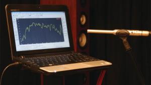
Step 5: Let 'er Rip The sub's controls should make it easy to optimize its performance for your room and setup. The variable low-pass crossover has a gain control for matching a preamp's output, and there's a dial for setting the crossover frequency (from 30 to 200 Hz). The parametric EQ has a rotary frequency control (for applying a boost or cut to a specific frequency between 18 and 80 Hz), a bandwidth control (to set how wide the EQ curve will be, within a range of 0.1 to 1.0), and an EQ level control, which lets you apply a boost (+6 dB) or cut (-14.5 dB) at the selected frequency and bandwidth. You can remove the EQ from the signal path by setting it to 0. And you'll also find a 6-dB notch filter that Parts Express says can significantly improve the sub's performance.
Based on my admittedly brief demo time, the Titanic subwoofer seems like a real value, providing a sizable, well-defined bottom end that's nicely suited for home theater use. Simply put, it sounds a lot more expensive than it is. I'll let you assign the value of being able to say you built it yourself.
Read the last Step by Step Back to Homepage What's New on S&V
- Log in or register to post comments


| Displays Electronics Speakers | Sources Other Gear Software | Top Picks of the Year Top Picks | Custom Install How To Buy How To Use |
Tech 101
|
Latest News Features Blogs | Resources Subscriptions |
WHERE TECHNOLOGY BECOMES ENTERTAINMENT
 © 2024 Sound&Vision
AVTech Media Americas Inc., USA
All rights reserved

